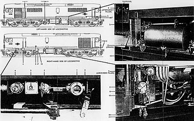
Fig. 7. Controls and gauges outside the locomotive
The normal working of the locomotive is controlled from the selector and power shafts of the master controller, and from the brake valves and dead-man switches. The locomotive's direction is chosen by the selector shaft, and the power at which the engine works by the power shaft. All other functions are performed automatically by the control equipment. The power shaft has ten notches giving progressive increases of power; notch 10 corresponds to the full load.
The two shafts are mechanically interlocked, and the controller can be locked in the OFF position by a removable key. A key switch on the driver's switch panel controls the supply to the control equipment and certain auxiliary machines.
The main generator supplies five traction motors in a permanent parallel combination, with an electro-pneumatic contactor in each motor circuit. An electro-pneumatic reverser reverses the electrical connections to the traction motor fields when a change in direction is required.
Two electro-magnetic contactors connect the battery to the main generator when the ENGINE START button is operated.. and the generator functions as a motor to turn the engine. Earth leakage relay protection is incorporated for the traction circuits.
The battery, cooler fan motor, lubricating oil-cooling water pump motor, two exhauster motors, fuel transfer pump motor, and two traction motor blower motors are connected to the auxiliary generator.
A vibrating, carbon-type voltage regulator maintains the auxiliary generator voltage at 110V over the full traction speed range of the engine. A switch, operated from either inside or outside the locomotive, isolates the battery from the auxiliary generator, auxiliary machines and control equipment. External charging is done through two battery-charging sockets.
A rotary changeover and isolating switch supplies the locomotive lighting from either the battery or an external 110V d.c. or a.c. supply.
Any one motor, or all five, can be cut out by the cut-out switch, which is locked in the desired position by the master controller key.
An automatic servo-mechanism prevents under- or over-loading of the engine by a signal from a hydraulic valve connected to the engine fuel lever. This actuates a servomotor regulator which regulates the electrical load; total engine power output, which depends on the notch position of the master controller, is thus kept constant, irrespective of changing speed and load conditions.
Deadman's Device
The deadman's device is a safeguard against accidents in case the driver is incapacitated. After a time delay, power is cut off from the traction motors, the diesel engine speed is reduced to idling, and the locomotive and train brakes are applied whenever either the deadman's pedal or push-button in the cab concerned is released.
Brake and Air Equipment
The brake is controlled by two driver's brake valves. One, the train-brake valve, actuates the train vacuum brakes, with a simultaneous and proportional application of the locomotive air brake; the second, the locomotive brake valve, applies only the locomotive brakes. The proportional application can be released by operating the locomotive brake-release foot-switch.
Fig. 7. Controls and gauges outside the locomotive
(Right-hand Side of Locomotive)
(1) Lighting isolator and changeover switch
(2) External handle of battery isolating switch
(3) Fire alarm reset button
(4) Wheel wear compensator
(Left-hand Side of Locomotive)
(14) Four isolating cocks for straight air-brake bogie hoses, main reservoir and refuelling reducing valve.
(15) Two main and brake-operating reservoir drain cocks
(16) Two fuel drain and filter isolating valves
(17) Boiler blow-down connection
(19) Fuel drain connections
(Both Sides of Locomotive)
(5) Fire extinguisher control
(6) Battery charging sockets
(7) Shed lighting sockets
(8) Refuelling light switch
(9) Refuelling lockheed and emergency fillers
(10) Refuelling air connection
(11) Lubricating oil fill and drain connection
(12) Boiler water filling and draining connection with valves
(13) Radiator filling and draining connection with valves
(18) Engine room floor drain connection
(a) Fuel level gauge
(b) Boiler water level gauge
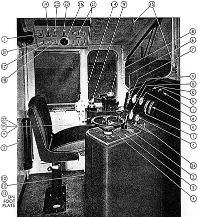
Fig. 8. Controls, instruments and gauges in the driver's cab
(Driver's Controls in Each Cab)
(1) Control switch key (removable and carried by driver)
(2) Master controller locking key (removable and carried by driver)
(3) A.T.C. change end switch key (removable and carried by driver - when fitted)
(4) A.T.C. reset button (when fitted)
(5) Master controller with selector shaft handle (positions FORWARD, OFF, ENGINE ONLY and REVERSE marked) and power shaft handwheels (Notch positions OFF to 10 marked)
(6) Engine start push-button
(7) Engine stop push-button
(8) Vacuum-brake valve (handle positions marked NEUTRAL, RELEASE, RUNNING, LAP, SERVICE BRAKE and EMERGENCY)
(9) Air-brake valve
(10) Deadman's pedal (at driving position)
(11) Deadman's push-button (at assistant's position)
(12) Sanding pedal
(13) Locomotive brake release pedal
(14) Two two-tone horn valves (one at driver's position; one at assistant's position)
(15) Two window wipers with control valve (one at driver's position; one at assistant's position)
(16) Cab-heater switch
(17) Demister switch
(18) Foot-heater switch
(19) Cab light switch
(20) Instrument light switch
(21) Boiler isolating switch (normally ON)
(22) Overload reset button
(23) Six marker switches
(24) Four instrument and warning light dimmer controls
(25) Fire extinguisher control
(26) Hand-brake handle
(27) Isolating cocks for horns (inside driver's desk, accessible through cover)
(Instruments & Gauges in Each Cab)
(a) Vacuum gauge
(b) Duplex bogie air pressure gauges
(c) Main reservoir and direct air-brake duplex pressure gauge
(d) Speedometer
(e) Main generator ammeter
(f) Engine speed indicator
(g) Engine stopped indicator light (red)-normally dim, bright on fault
(h) Wheel slip indicator light (amber)-normally dim. The wheel slip device is not fitted to the AEI locomotive, so this light is bright only when operating in multiple with another type which is slipping.
(j) Fault indicator light (blue)-normally dim, bright on fault, repeats generator compartment fault indicators.
(k) Train-heating pipe pressure gauge
(I) A.T. C. indicator (when fitted)
(m) A.T. C. bell (when fitted)
(n) A.T.C. horn (when fitted)
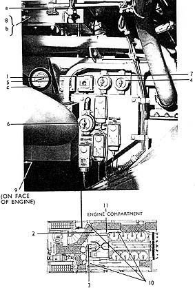
Fig. 9. Controls and gauges in engine compartment
Controls in Engine Compartment
(1) Local engine start button
(2) Emergency engine stop/start lever
(3) Engine avers peed trip reset handle
(4) Fuel transfer pump TEST switch
(5) Main water pump TEST button
(6) Cooler fan control switch (sealed in AUTO position)
(7) Shut-down thermostat cut-out switch (sealed in NORMAL position)
(8) Emergency fuel changeover cock
(9) Engine fuel isolating valve
(10) Three lubricating oil-cooling water drain valves
(11) Lubricating oil-filling and -draining valve
Gauges Fitted in Engine Compartment
(a) Water header tank level gauge
(b) Fuel header tank level gauge
(c) Engine lubricating oil-pressure gauge
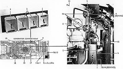
Fig. 10. Controls, instruments and gauges in the generator compartment
Controls in Generator Compartment
(1) Braked/unbraked selector switch
(2) Two exhauster isolators
(3) Engine isolator
(4) Compartment lights switch
(5) Boiler control switch
(6) Boiler Fluestat reset button
(7) Boiler lockout reset button
(8) Battery/auxiliary generator voltmeter changeover switch
(9) Battery-isolating switch
(10) Fire alarm reset and test buttons
(11) Control reservoir isolating valves
(12) Two deadman isolating cocks (one air, one vacuum, both sealed)
(13) Main steam stop valve
(14) Boiler blow-down valve
(15) Boiler feed-water check valve
(16) Three boiler water gauge cocks
(17) Boiler air damper door
(18) Nine isolating cocks for triple valve, sand~rs, control, compressor and vacuum governors, and control air reducing valve
(19) Fire extinguisher thumb-screw and split pins (must be removed before the apparatus is operational)
(20) Boiler fuel-isolating valve (not shown)
Instruments and Gauges in Generator Compartment
(a) Main generator ammeter (above control cubicle door)
(b) Main generator voltmeter (above control cubicle door)
(c) Battery/auxiliary generator voltmeter (above control cubicle door)
(d) Battery charge/discharge ammeter (above control cubicle door)
(e) Fault indicator lights (red)-normally dim, bright an fault.
Reading from left to right:-
(i) Overload or earth fault (normal/tripped)
(ii) Cooling water temperature (normal/high)
(iii) Blowers (running/stopped)
(f) Control air pressure gauge (opposite control cubicle door)
(g) Boiler pressure gauge (on boiler)
(h) Boiler water gauge (on boiler)
(j) Boiler low water alarm lamp (normally dim, bright on fault) (on boiler)
(k) Boiler lockout indicator lamp (normally dim, bright an fault)
On some locomotives, the boiler control panel has been repositioned above No.2 traction motor blower. items 5, 7, j, and k are affected, as they are part of this panel.
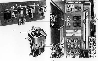
Fig. 11. Apparatus of the Control Cubicle
(1) Motor cut-out switch (released with master controller locking key)
(2) Overload and earth fault panel with indicator flags. Flags show Red when normal, and White when tripped
(3) Earth fault isolating switch (sealed in NORMAL position)
(4) Nineteen miniature circuit-breakers (function and rating as labelled). (Toggle is down for ON, up for OFF)
(5) Fuses; auxiliary generator (800 amp), battery (250 amp), main generator excitation (125 amp), lubricating oil-cooling water pump set (35 amp), exhauster and blowers (60 amp), main pump set (125 amp), voltmeter (2 amp), cooler fan (160 amp)
No spare fuses for the above are carried on the locomotives. If a fuse ruptures, the matter should be reported at once. The defective fuse must not be replaced until the cause of the rupture has been thoroughly investigated. Severe damage to machines or apparatus may be caused otherwise.
A spare fuse of each type is carried, and these can be changed if necessary; boiler fuses (on boiler control panel, low down on the right-hand side), magneto motor fuse (5 amp), boiler and feed-water pump (20 amp)
The Water System
The water system consists of two separate circuits. The engine jacket-cooling water circulates through the jackets and sections of the radiator panels. A water-pressure switch connected to the pressure side of the water pump ensures that, if water pressure is lost, the engine will be shut down. Five thermostat elements are mounted in the outlet pipe from the A Bank cylinder block. Three control radiator-fan motor spced; another lights a warning lamp in the generator compartment (which in turn lights the ALARM LAMP in the cab) at a water temperature of l90°F, and, if the water temperature rises to 195°F, a further element shuts the engine down. The water used should be either distilled or adequately treated to prevent corrosion.
The other circuit in the system is the lubricating oil-cooling water, which circuLites through the lubricating oil-cooler. and through the corresponding section of the radiator panels.
The Lubricating System
Two gear-type pumps circulate oil through non-return valves, Vokes full-flow felt-type filters, the lubricating oil-cooler and the engine.
The main pump is engine-driven, and delivers about 90% of the total oil flow. The auxiliary pump, which is electric. is used to prime the system before starting the engine and to circulate oil after shut-down. A magnetic filter of the Phillips type is fitted on the delivery side of the auxiliary pump.
A pressure switch set at 5 lb/in2 ensures that the engine cannot be started until the system is fully primed. A similar switch shuts the engine down if the pressure falls below 25 lb/in2.
The equipment is filled and drained by a pressure connection to Lockheed 1.1/4 in. fillers, and by opening a valve in the locomotive.
The Fuel System
A motor-driven transfer pump delivers fuel to the delivery manifold in the locomotive roof; from here the fuel is taken to the engine pumps and injectors through a Vokes duplex filter and the overspeed trip, which cuts off the supply if the engine overspeeds. The excess fuel fills the service tank, and supplies the boiler. The surplus is returned to the main tank.
The fuelling is carried out by a pressure connection to Lockheed 1.1/4 in. fillers. Emergency fuelling can be done through the filler on either side of the tank. A drain valve is fitted on the bottom of the tank (Fig. 17).
A Smith's Desynn-type fuel gauge is mounted in the tank. The tank's capacity is 575 gallons.
Locomotive Data & Performance
Description
Driver's Controls, Instruments and Gauges
Driving Instructions
Special Instructions
Boiler Operation
General Maintenance & Lubrication Schedules