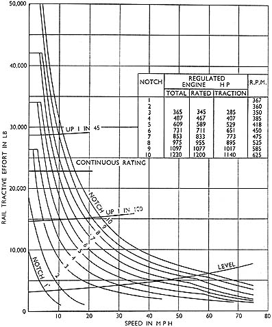
Fig. 4. Performance Curve of the locomotive (with train resistance for 420 tons trailing load of passanger stock)
Fig. 4. Performance Curve of the locomotive (with train resistance for 420 tons trailing load of passanger stock)
The performance of the locomotive on the ten notches of the master controller is shown in Fig. 4.
On notch 10, full power is maintained over a speed range of approximately 4.3 m.p.h. to 61 m.p.h., covered by generator voltage control up to about 25 m.p.h., and after that bv traction motor field weakening.
On notches 3 to 10, at speeds below full power range, tractive effort is limited to the maximum for that notch by a current limit relay. At speeds above full power ninges, the tractive effort decreases in accordance with the inherent characteristics of the motor at sensibly constant voltage and weak field.
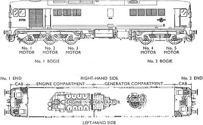
Fig. 5. Identification of ends and main components
The locomotive ends are called No. 1 and No. 2. and the sides left-hand side and right-hand side, as shown in Fig. 5.
The underframe, side walls, cantrails, and fuel and water tanks, are a complete fabricated structure.
The body is divided by transverse bulkheads into four compartments. The bulkhead separating the engine and generator compartments is removable. Interchangeable panel-type air filters are built into the framework of the engine air intake behind hinged louvres. Sections of the roof are detachable, so that the engine-generator-compressor set, boiler, and auxiliary machines can be removed. There are marker lights and discs to British Railwavs standards at each end.
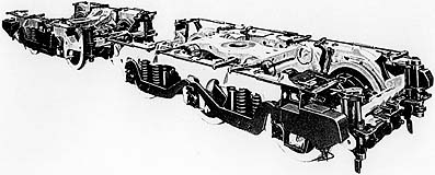
Fig. 5. Bogies of the five-axle locomotive
The bogie frames (Fig. 6) are one-piece steel castintzs of the General Steel Castings Corporation type, and have a swing bolster and equalised coil spring suspension with Woodhead-Monroe dampers. The wheels are the Baker Bessemer pressed-disc type, with a tyre profile to British Railways standard.
The axle-boxes are the oil-lubricated Hoffman roller bearing type, with pads for end-location of the axle. The No. 3 axle-box cover on the left-hand side carries the mileometer; the No. 4 axle-box cover on the right-hand side carries the speedometer generator.
The five axles are each driven by an axle-hung, nose suspended traction motor; three are in one bogie, and two are in the other. The motor is secured to the bogie transom at the nose by a Silent-bloc bushed link. A similar link between the motor frame and the bogie side-frame locates it sideways.
The braking equipment is Metcalfe-Oerlikon, using air brakes on the locomotives, and vacuum brakes on the train. Clasp brakes are fitted on all wheels, the rigging being operated by five cylinders equalised throughout.
The ejectors for the electro-pneumatic sanding equipment are placed in front of the leading wheels for both directions.
Diesel Engine
The diesel engine is the Crossley Brothers two-stroke cycle, eight-cylinder, HSTVee8 type. No cylinder-head valves or valve-operating gear are used, because the engine is the port-controlled loop scavenge type, with exhaust pulse pressure charging.
A scavenge blower, built into the engine, draws combustion air from a three-panel filter group in the locomotive side, and delivers it to the air manifolds.
Wet chrome-plated cylinder liners are used with cast-iron oil-cooled pistons; the cylinder heads are of aluminium alloy.
The fuel pumps are Crossley type, of monobloc construction, with one block for each cylinder bank. Injectors are made by Crossley.
A chain-driven lubricating oil pump of the gear type, built into the engine, supplies oil under pressure through an oil-cooler to the main bearings, connecting rod, big and little end bearings, to the pistons for cooling, and to other moving parts. Two reciprocating balance weights, one mounted at the free end of the engine and the other at the end of the auxiliary generator, where it is combined with the locomotive compressor, correct any primary out-of-balance.
Generator Set
The generator set is a single-bearing machine, with the two armatures mounted on a common shaft, carried on a single roller bearing at one end, and solid-coupled to the diesel engine crankshaft at the other.
The frame of the auxiliary generator is spigoted to that of the main generator, and the set is flange-mounted to the engine base to form a rigid unit. This is carried by the locomotive frame on a three-point resilient suspension of the Metalstik Dyna-focal type.
The main generator is separately-excited and counter-compounded; the series winding is also used for starting the engine by motoring the main generator from the battery. it supplies the five traction motors in a permanent parallel combination.
The auxiliary generator is a separately-excited machine, with its output regulated at 110V, except at the low idling speed. It supplies power for the battery-charging, lighting, cab-heating, main generator-excitation and train-heating boiler.
The set is self-ventilated by a fan at the engine end of the set on the engine side of the partition bulkhead.
Traction Motors
The traction motor is axle-hung and nose-suspended; two axle sleeve-bearings with a resilient gearwheel are used in the drive. The motors are force-ventilated by the traction motor blowers, and the air passes into each motor through ducting in the underframe and through flexible rubber bellows.
Main Pump Set
The main pump set consists of a 110V electric motor with shaft extensions at both ends. The jacket water pump is built on the end of the motor furthest from the commutator, the casing is flange-mounted to an extension of the motor frame, and the impeller is fixed to the tapered shaft end. The jacket water pump circulates the water through the engine cylinder blocks and jacket water sections of the radiator.
At the commutator end, the auxiliary lubricating oil pump is mounted on an extension of the motor yoke, with the drive taken through a Renold-type flexible coupling. The pump works in parallel with the engine-driven pump.
The set starts as soon as the controller is moved to ENGINE ONLY, and is operated from the battery to build up lubricating-oil pressure before the engine is started. When the engine is running, the pump set continues to run, but at higher speed. When the engine is shut down, the pump set returns to the lower speed and runs unti[ the controller is moved to OFF.
Lubricating Oil-cooling Pump Set
The lubricating oil-cooling pump set is similar in arrangement to the main pump set, with the water pump built on the motor end furthest from the commutator. It circulates water through the lubricating oil-cooler on the B bank side of the engine, and the lubricating oil-cooling water sections of the radiator.
The crankcase exhauster is mounted on the commutator end, with the casing attached to the motor yoke and the impeller fixed to the motor shaft. It draws the crankcase gases through an oil separator, and discharges them through the locomotive floor; it thus maintains a slight vacuum in the crankcase and keeps down the risk of an explosion.
The set operates from the 110V supply whenever the engine is running.
Fuel Transfer Pump Set
The fuel transfer pump set is a motor with shaft extensions at both ends which drives the fuel transfer pump and the load regulator servo oil pump. It operates normally from the 110V supply whenever the engine is running, but can also be driven from the battery for priming the fuel service tank, testing the load regulator system or running the boiler.
The fuel transfer pump is flange-mounted to a coupling chamber on the motor end-plate furthest from the commutator, and driven through a Renold flexible coupling. The pump draws fuel from the main fuel tank in the underframe and delivers it to the fuel delivery manifoN. A rehef valve spills excess fLiel back to the main ~ank when the service tank is full and the pressure is more than 8 lb/in2.
The load regulator servo oil pump is similarly mounted on the commutator end of the motor, and provides oil pressure at the engine pilot valve for operating the load control apparatus.
Engine-cooling Equipment
The engine-cooling equipment consists of two radiator panels. one in each side of the body, connected by air ducting to a motordriven vertical-axis fan in the roof. The thermostaticallv-control led fan runs at speeds such that the engine-water temperature is approximately the optimum operating temperature.
The double bank-type radiator panels have nine sections for the lubricating oil-cooling water on the outside, and nine sections for the jacket water inside. The removable sections are streamlined section tubes threaded through and bonded to a number of copper thermoplates.
The fan runner is fabricated mild steel.
Traction Motor Blower Fans
Motor-driven centrifugal fans, one at each end of the locomotive, ventilate the motors in the corresponding bogies and operate the demisters in the cab.
Fan runners are fitted to taper-shaft extensions on the serieswound motors with the fan casings mounted on the blower support independently of the motor. The blowers are operated from the 110V supply whenever the engine runs, but can be shut down when the controller is in the OFF position.
Vacuum Exhausters
The vacuum exhausters are vertical four-cylinder machines, with the driving motor arranged for two-speed operation. The motors are flange-mounted on the end of the crankcase, and the armature is carried on an extension of the crankshaft. The motors are series-wound and operate from the 110V supply. They are rated for continuous operation at both maintaining and release speeds, and can be operated continuously at the higher speed under emergency conditions of excessive leakage.
Air Compressors
The air compressor is a two-cylinder vee, single-stage, air-cooled machine, flange-mounted to the auxiliary generator end-shield and driven from a shaft extension. It is integral with the dynamic balancer unit, and the single crankpin is used to drive both the compressor and the balance weight, which is housed in a chamber between the auxiliary generator and compressor.
The compressor governor operates an unloading mechanism on each cylinder head through the compressor relief magnet valve, so allowing the compressor to run light when the pressure in the main reservoir reaches its maximum, and to pump when it falls to a pre-determined value.
The compressor and balancer crankpin is arranged so that it can be removed by the oil injection process.
Battery
The battery is of the lead-acid, low-resistance, diesel-starting type, arranged in three-cell monoblocs, and housed in two boxes, one each side of the locomotive. Each cell is fitted with bolted terminal connectors and electrolyte level-indicator plugs. The battery starts the engine by motoring the main generator, and supplies the auxiliary lubricating oil pump, control equipment, train-heating boiler, and lighting, when the diesel engine is not running. It is automatically charged from the auxiliary generator.
Train Heating Boiler
The boiler for heating the train is automatic and oil-fired. Water is drawn from the tank in the underframe by a motor-driven feed pump, controlled by a magnetic float level switch in the boiler.
The oil burner is supplied with diesel fuel from the fuel service tank by a motor-driven pump, which also drives the burner fan. Combustion air is taken by ducting from the air-settling chamber, and combustion conditions are controlled by a damper door.
The oil is ignited by a spark between electrodes placed close to the burner jet; the spark is produced by a magneto which runs for a short time whenever the burner motor starts up. Varying steam demands are met by the ON/OFF control system which maintains the pressure within required limits. In addition to the safety valve, a low-water and no-flame cut-out safety device stops the boiler from being put back into service until the trouble has been corrected.
The steam is delivered to the train-heating pipe through a main steam-stop valve and a pressure-reducing valve, which limit the train pipe pressure.
Controls and motors are normally supplied from the 110V supply, but they can be operated from the battery when required.
Air Filters
The engine combustion air is filtered by panel-type elements secured by quick-release catches to framing in the body sides, and protected by hinged louvre doors.
Locomotive Data & Performance
Description
Driver's Controls, Instruments and Gauges
Driving Instructions
Special Instructions
Boiler Operation
General Maintenance & Lubrication Schedules