General Maintenance Schedule

If the locomotive is inspected regularly and methodically, the cost of repairs will be kept low, and the life of the equipment lengthened. The procedure recommended in this section should, however, be used as a guide, until operating experience shows what intervals may be used safely. For example, the lubrication of the bearings of electrical machines depends on the needs of the service, and should be determined from controlled observations on several locomotives.

It is assumed that, on average, the locomotive will cover about 300 miles per day, and that the diesel engines will run for about 100 hours per week.

For engine air fitter panels and fuel pump parts, etc., it will be more satisfactory to exchange them for ready-cleaned or reconditioned parts.

For the boiler, the schedule is drawn up on the assumption that the boiler is in full-time operation.


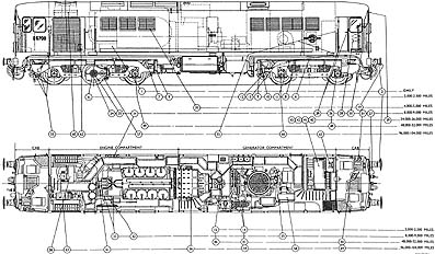
Fig. 13. Lubrication Diagram

Daily
Check the fuel, water and lubricating oil supplies. Check that there are no leakages of fuel, lubricating oil, servo oil, or water, and that the drain cocks are securely closed.

Engine
Check as far as possible that the exhaust colour and lubricating oil pressure are satisfactory.

Check that all cylinders are cut in, with their lever points down, and that the overspeed trip is latched in the correct position.

Control Equipment
(1) Test the lights.
(2) Check that the covers are on all electrical equipment.
(3) Check that the motor cut-out switch is at the ALL MOTORS IN position.
(4) Check that the earth-fault relay-isolating switch is at the IN position, and that the sealing wire is intact.
(5) Check that the fuel pump TEST switch and the high-water temperature shut-down switches are at NORMAL, and that the sealing wire on the latter is intact.
(6) Check that the cooler fan control switch is at AUTO, and the sealing wire is intact.

Brake and Air Equipnient
(1) Check the operation of the hand-brake and the air and vacuum brakes.
(2) Check that the deadman's air and vacuum isolating cocks are in their normal positions, and that the sealing wires are intact.
(3) Check that all air and vacuum cock handles are in their correct positions.
(4) Check the horns.
(5) Check the sanders and sand supply.

Mechanical Parts
(1) Check that the interior is tidy.
(2) Inspect the running gear.
(3) Check that the louvre doors over the engine filters and radiators are securely closed.
(4) Check that the fire equipment is in order.

Boiler
Operate the blow-down valve and check the operation of the low-water cut-out device.

Lubrication
See figure 13 (above)

Weekly = 2000 to 2500 miles = 100 hours
Daily routines plus :-

Engine
(1) Fuel suction filter - Remove and clean
(2) Air intake filters - Remove and clean at every second examination

Control Equipment
(1) Battery - Add distilled water to the battery cells, and read the specific gravity of the pilot cells.
(2) Starting contactors - Examine, clean and renew the starting contacts as necessary

Brake and Air Equipment
(1) Hose couplings and connections - Examine
(2) Reservoir drain cocks, drip cups, etc. - Blow out

Mechanical Parts
(1) Loose equipment - Check that tools, etc., are on the locomotive
(2) Tyre profiles - Examine

Boiler
(1) Burner electrodes - Remove, clean, and reset if necessary
(2) Burner jet - Remove and clean
(3) Safety valve - Check the blow-off pressure
(4) Auto-clean filter - Turn the handle one complete revolution

Lubrication
See figure 13 (above)

Monthly = 8000 to 9000 miles = 500 hours
Weekly routines plus :-

Engine
(1) Cylinder heads - Inspect for signs of blowing. Nuts to be checked for torque
(2) Air transfer valves- Change for reconditioned set
(3) All chain drives - Check for correct tension and broken links
(4) Fuel pipes (pump to injector) - Check for leakage and loose clips
(5) Duplex fuel filter (Vokes) - Remove the element of the primary filter, and examine it. If wax is present, throw out the primary element and replace it with a secondary element. Fit new secondary element.
(6) Lubricating oil filters (Vokes) - Remove the elements, and examine them.
(7) Water - Take a sample for chemical analysis
(8) Diesel engine sump - Take a sample of oil for chemical analysis, and change it if necessary. (120 gallons needed for an oil change)
(9) Silencer - Remove the two drain plugs and drain off any oil

Control Equipment
(1) Engine speed regulator - Check its operation, and lubricate the cylinders
(2) Load regulator - Check the operation of the control valves, and examine the contacts
(3) Battery relay - Check that it moves freely, and clean the contacts, if necessary
(4) Voltage regulator - Check the contact gap and voltage setting
(5) Battery - Clean the cell tops if necessary, check the tightness of the terminals, and apply vaseline if necessary.

Electrical Machines
(1) Commutator covers - Brush away all loose dirt, especially on traction motors, and remove the covers
(2) Brushgear - Remove the brushes from their holders and clean them with a lint-free rag. Examine each brush, and replace any which are worn to the minimum length, seriously chipped, or have badly frayed flexibles. Check that the brush flexibles are firmly secured, both into the brush and into the holder
(3) Replace the brushes, and, if necessary, clean the holders so that the brushes slide easily in them
(4) Bed new brushes to the commutator
(5) Clean the porcelain insulators and examine them for cracks looseness, or metallised surfaces. Replace the complete brush-holder if the porcelains are defective
(6) Commutators - Examine for signs of burning, scoring, flashover, etc. Clean the surface of the Vee-ring and the insulation over the risers
(7) Arcing horns - Examine the horns on the traction motor. If they are burned, replace them and set the gap to 0.4in.
(8) Remove any dust which has collected in the commutator chamber, and replace the commutator covers

Brake and Air Equipment
(1) Brake cylinders - Check the piston travel and adjust the linkage or renew the blocks as required. See Fig. 12. (below)


Fig. 12. Brake Adjustment Diagram

(2) Snifter valve - Dismantle, clean and test after reassembly
(3) Strainers - Clean all air and vacuum system strainers, including those of the compressor and exhausters
(4) Compressor, vacuum and control governors - Check that they are set correctly
(5) Safety valve - Check that it is set correctly
(6) Reducing valves - Check the setting of the control-air and refuelling-air pressure-reducing valves
(7) Exhausters - Check the lubricating-oil pressure
(8) Vacuum brake - Test for correct efficiency in line with standard procedure

Mechanical Parts
(1) Generator compartment - Clean out the air settling chamber
(2) Radiators - Clean the air side of the panels and ducting
(3) Gauge glasses - Clean the engine-water header, the fuel service, and boiler-water tank gauge glasses.
(4) Fuel tank - Drain off any water and sludge from the bottom of the tank
(5) Draw and buffing gear - Inspect

Boiler
(1) Burner - Generally examine, clean and adjust as necessary to ensure good combustion
(2) Fuel filter (Vokes) - Remove and clean the element
(3) Pressure switch - Check that it is set correctly
(4) Flue chamber and fire tubes - Examine and clean as necessary
(5) Fluestat - Remove, clean and check its operation
(6) Water space - Examine the surfaces through the sight holes and the mudhole doors, and clean them as necessary
(7) Float switches - Remove and clean as necessary

The instructions for items 6 and 7 are provisional until the correct water treatment has been determined.

Lubrication
See Figure 13. (above)

Three-monthly = 24000 to 26000 miles = 1250 hours
Monthly routines plus :-

Engine
(1) Lubricating-oil magnetic filter - Remove and clean
(2) Blower-oil supply filter (inside the free end casing) - Remove and clean the element
(3) Fuel sprayers - Examine and adjust if necessary
(4) Overspeed trip - Check its operation

Control Equipment
(1) Electro-pneumatic motor switches and reverser - Clean the switch contacts if necessary, and examine and lubricate them
(2) Reverser - Clean and lubricate the contacts and cylinders
(3) Starting contactors - Clean and examine
(4) All low-tension contactors - Clean and examine
(5) All interlocks, including the master controller and the brake valve contacts - Clean and examine
(6) All relays - Clean and examine
(7) Motor cut-out switch - Clean and examine
(8) Load regulator - Clean and examine, drain off the surplus oil, and, if it is excessive, examine the pistons
(9) Ammeters and voltmeters - Check that the zero setting is correct, and adjust it if necessary
(10) Warning and shut-down devices - Check for correct operation
(11) Battery-isolating switch - Clean the blades and lubricate the hinges and external operating gear
(12) All control apparatus - Check that all connections and fixings are tight

Electrical Machines
(1) All machines - Blow out and inspect the interiors as thoroughly as possible. Check that all brushgear bolts are tight
(2) Traction motors - Check that the bolts securing the axle caps, gear-cases, axle-shields, dust-guards and cable cleats are tight. The lids of the oil wells must fit correctly. Check that the lubricating yarn in the suspension bearings is tightly packed, and add more if necessary. Check that there is no leakage from the gearcase. Examine the external cables for chafing, and examine the flexible air inlet bellows. Examine the nose suspension and lateral restraint links, and check that the rubber bushes are clean and in good condition. Check the diametrical clearances of the axle suspension bearings
(3) Main generator - Examine the coupling between the engine and generator

Brake and Air Equipment
(1) Gauges - Test the air and vacuum gauges against the master gauges
(2) Exhauster and compressor - Inspect the suction and delivery valves. Replace the exhauster filters

Mechanical Parts
(1) Bogie shock absorbers - Examine for signs of leakage
(2) Engine-generator mountings - Generally examine. Clean the exposed surfaces of rubber
(3) Check that the fixing bolts of radiators, machInes and piping are tight
(4) Control air filter - Clean

Boiler
(1) Water feed pump - Adjust the glands and repack them if necessary. Examine the belt drive
(2) Fire tubes - Check that there is no leakage at the tube plate joints, and expand if necessary
(3) Safety valve and pressure gauges - Test against the master gauge

Lubrication
See Figure 13. (above)

Six-monthly = 48000 to 52000 miles = 2500 hours
Three monthly routines plus :-

Engine
(1) Exhaust pipes - Examine
(2) Air ports, exhaust ports, and manifolds - Clean if necessary
(3) Cylinder heads - Remove and clean out the water space
(4) Pistons - Clean and examine the tops
(5) Fuel pumps - Examine the rocker levers, pins and rollers, etc.
(6) Duplex fuel filter (Vokes) - Fit a new primary element and clean the secondary element
(7) Governor - Examine the external linkage and check that it moves freely
(8) Lubricating-oil pump - Examine
(9) Lubricating-oil filters - Fit new elements and seals
(10) Water spaces - Examine

Control Equipment
(1) Master controller - Examine the fingers and mechanical interlocking, and lubricate
(2) All resistances - Blow out
(3) Interlocks - Adjust if necessary
(4) Switch panel and push switches - Remove and examine the covers
(5) Battery - Give a conditioning charge
(6) Insulation test - Megger all controls except the fuel gauge and the speedometer

Brake Auxilliary Equipment
(1) Sand ejectors - Clean the chokes and strainers
(2) Brake valve contacts - Examine and lubricate
(3) Compressor - Replace the valve strips and examine seats
(4) Exhauster - Clean the oil strainers after draining the sump

Mechanical Parts
(1) Axle-boxes - Inspect after draining. Check the float between box and guides, and measure the thrust-pad wear
(2) Bolster swing links - Check the wear of the bottom cotters
(3) Fire extinguishers - Check the weight

Boiler
Control panel - Remove the cover and examine and clean the apparatus as required

Lubrication
See Figure 13 (above)

Annually = 96,000 to 104,000 miles = 5000 hours
Six monthly routines plus :-

Engine
(1) Examine all moving parts
(2) Check all settings and adjustments in line with the technical data
(3) Pistons - Remove, clean, and replace worn piston rings
(4) Bearings - Examine all bearings and check the running dearance
(5) Cylinder liners - Examine
(6) Fuel pumps - Examine springs, control valves, plungers, etc.
(7) Lubricating oil-cooler - Clean out the water and oil spaces
(8) Governor - Examine all parts
(9) Chains and sprockets - Examine all parts
(10) Auxiliary lubricating oil-pump - Dismantle, clean and examine
(11) Fuel transfer pump - Dismantle, clean, and examine
(12) Load-regulator servo-system pump - Dismantle, clean and examine
(13) Water pumps - Examine

Control Equipment
(1) Fuses - Check that the ratings are correct
(2) Magnet valves - Remove the valve interiors, and clean and examine
(3) Cab heaters - Examine the short lengths of cable between the heater and terminal box, and replace if the insulation is perished
(4) Voltage regulator - Examine the knife-edge bearings
(5) Load-regulator - Replace the worn contacts and piston washers
(6) Cooker - Clean the base reflectors
(7) Battery - Remove and clean. Recondition the terminals, and test the battery

Brake and Air Equipment
(1) Carry out the tests prescribed in the brake section to find out which apparatus is not up to the required standard of performance
(2) Dismantle, clean, examine and lubricate as necessary all faulty brake and air equipment, and the exhausters and compressor
(3) Renew the rubber parts in the brake valves as necessary

Few replacements are to be expected after one period, and after two periods replacements will probably be confined to 'O' Rings, seals and gaskets

Mechanical Parts
(1) Clean the mechanical structure thoroughly and inspect for signs of fatigue
(2) Clean and inspect the centre pivots, side bearer faces, bolster thrust faces, brake pins, and axle-box guides
(3) Traction-motor air ducts - Inspect as far as possible
(4) Radiator fan - Remove and inspect the keyway
(5) Filter spring catches - Examine and repack with grease
(6) Oil piping - Clean
(7) Fuel tank - Clean and flush
(8) Boiler-water tank - Clean and flush
(9) Load-regulator servo-system - Clean the filter and tank
(10) Window wipers - Overhaul
(11) Mileage counter - Examine
(12) Speedometer generator - Examine and repack the bearings
(13) Battery boxes - Clean and repaint

Boiler
Remove, clean and inspect all mountings, and inspect boiler shell and tube plates thoroughly for signs of fatigue. Carry out hydraulic pressure test before rebuilding

Lubrication
See Figure 13 (above)

General overhaul (At approxi. 3-year intervals.)

Engine
With the engine-generator set removed from the locomotive, and the generator removed, dismantle all moving parts (crankshaft only if necessary), and recondition and adjust them where necessary. Renew all the filter elements. Test the engine on load after it has been reconnected to the generator.

Control Equipment

(1) All insulation - Clean, and repair any damage
(2) Electro-pneumatic motor switches and reverser - Dismantle, clean, examine, lubricate, and replace the piston washers. Reassemble and test
(3) Starting contactors and low-tension contactors - Replace worn hinge pins, etc., and retreat the coils by external brushing
(4) All relays - Replace the latch wearing parts if necessary
(5) Master controller - Examine for mechanical wear

Electrical Machines
Remove all machines from their mountings, and dismantle them according to the instructions on the individual machines.

Examine all parts thoroughly, and clean, renovate or renew as required. When they are reassembled, the machines should be run light long enough to ensure that the bearings fit correctly. If necessary, the machines should be dried out, and possibly revarnished and again dried out, before going back into service.

Mechanical parts
Dismantle all mechanical parts, and recondition and adjust them where necessary.

Boiler
Check the fire-tube thickness, and replace as necessary.

LUBRICATION-TOPPING-UP LEVELS
The correct levels are:-

Diesel Engine Sump
Between the FULL and REFILL marks on the dipstick (the dipstick is not screwed down), after priming and with the engine stationary.

Exhauster Sump
Between the top and bottom of the strainer in the oil filler, with the exhauster stopped.

Compressor and Dynamic Balancer Sumps
Between the high and the low marks on the compressor dipstick, with oil to the level of the level plug in the balance weight chamber. When filling the compressor, allow enough time for the oil to pass into the balance weight chamber before checking the levels.

Axle-boxes
When the levet plug is removed, it should be possible to see the oil rising up the plug hole.

Traction Motor Suspension Bearings
Between the MINIMIUM mark on the dipstick and the bottom of the filler pipe.

Traction Motor Gears
Between the MAXIMUM and MINIMUM marks on the dipstick.

Load-regulator
Between 3in. and 8in. from the top of the servo oil tank tank.

Boiler Feed Pump
Between the top and bottom of the dipstick.

Locomotive Data & Performance
Description
Driver's Controls, Instruments and Gauges
Driving Instructions
Special Instructions
Boiler Operation
General Maintenance & Lubrication Schedules